Gesture Controlled RC CAR
The Following project was completed to familiarize myself with the MPU6500 gyroscope and accelerometer sensor, as well as wireless communication between two arduinos using the NRF24L01 transceiver modules.
Application
A key component of automated machinery and logic involves communicating wirelessly between devices. The NRF24L01 transceiver module can be used in various projects such as this gesture-controlled RC car, controlling relays and PLCs, uploading data onto virtual clouds, or communicating with mobile phone applications.
The gyroscope on the other hand might seem to have limited uses, but is in fact found in popular gadgets such as drones for self-balancing, in phones for determining if the phone is in landscape or portrait orientation, and virtual reality (VR) headsets to predict viewing angles.
Implementation Details
NRF24L01 Transceiver Module
The NRF24L01 transceiver uses 2.4 GHz ISM frequency band to communicate. The Industrial, Scientific, and Medical (ISM) bands are used for unlicensed, low-powered devices such as mobile phones, Wi-Fi transceivers, and Bluetooth devices. This makes the NRF24L01 a suitable transceiver for any small to medium scale project. Note that a single NRF24L01 transceiver module can have up to 125 channels.
The NRF24L01 transceiver module uses a packet structure known as Enhanced ShockBurst. The structure is broken into five sections and can be seen in the picture below.
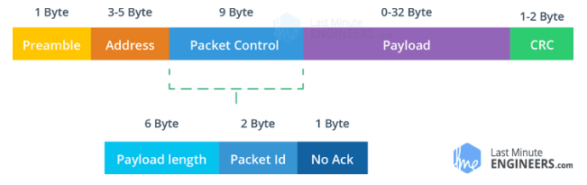
Preamble: A bit sequence used to synchronize the receiver’s demodulator to the incoming bit stream. It has the value of either 1 or 0. Essentially, ShockBurst packets are transferred by the carrier wave. if the preamble has a bit value of 1, then the transceiver will extract the packet from the carrier wave. if the preamble bit value is 0, then it will not be ignored.
Address: A unique field width assigned to each receiver.
Packet Control: The packet control has three functionalities. First being the Payload Length which determines the length of the payload (data transmitted). This field is only used if the payload length is dynamic. Second is Packet ID which assigns the packet a unique ID to determine if the packet is new or if it is a copy of a previous transmission. If the packet has been transmitted before, then it will be ignored. Lastly is the No Acknowledgement. If No Act is set to 0, then the receiver must transmit a packet back to the transmitter informing it that the original packet has been received.
Payload: The data shared between the transmitter and receiver.
CRC: A mandatory error detection mechanism. Informs the receiver if the packet was processed properly before being transmitted. Note that no packet is accepted by the receiver if the CRC fails.
MPU6500 Accelerometer / Gyroscope
The MPU6500 module consists of 3-axis gyroscope as well as an accelerometer along the 3-axes. The gyroscope is able to detect angular rotation using micro electro-mechanical system (MEMS) technology. When the gyros are rotated about any axis, a vibration is detected by the MEM within the MPU6500 chip. The MEM consists of a series of capacitors with small gaps in between them. As the MEM starts vibrating due to rotation/movement, the gap is increased and a change in capacitance is measured, which is then processed and transmitted to the microcontroller.
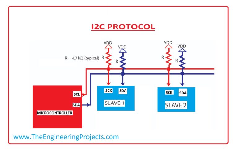
The MPU6500 module utilizes a bus to communicate with the microcontroller. The bus is called I2C which stands for integrated circuit (IC), and the 2 indicates that more than one chip is connected to the bus. The I2C uses two wired connections, serial data (SDA), and serial clock (SCL), to communicate between the master (Arduino) and slaves (MPU6500 and MPU9250 chips) as seen in the image below.
To establish communication between the master and slave(s), the 'slave address' and the 'register address' within the slave need to be identified. The image below contains an example of how data is read from the slave.
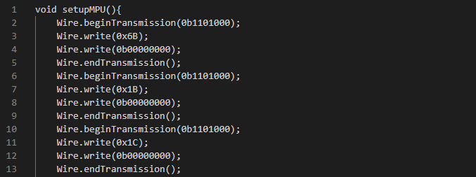
The command on line 2 calls for the slave address, followed by line 3 where the register address is identified. line 4 indicates the sensitivity and reading radius required. Lasty, line 5 ends the communication between the master and slave. Note that the module datasheet lists the slave addresses, register addresses, and settings.
Kuman KY58 L293D Motor Drive Shield
The Kuman KY58 is a motor shield drive capable of independently controlling 4 bidirectional DC motors independently. It has 2 L293D chips. An L293D consists of two H-bridge. The diagram below demonstrate how H-bridge circuits work.
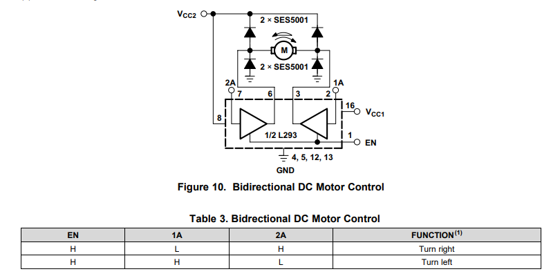
In an H-bridge circuit, there is a common ground, two independent power sources for the circuit and motor, an enabled for the op-amps, and inputs A1 and A2. The microcontroller, Arduino, controls the rotation direction by sending a Pulse Width Modulation (PWM) signal to either A1 or A2.
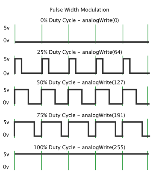
PWM is a technique for getting analog outputs with digital inputs. When a digital input turns on then off again, a square wave is created. The on-off pattern can simulate voltages ranging from full on(5V) to off(0V). The duration of "on time" is called the pulse width. To get varying analog values, the pulse width is increased/decreased as seen below.
Wiring and Coding
Transmitter Gadget
The transmitter gadget circuit consists of an Arduino Nano, an MPU6500 module, and an NRF24L01 transceiver module. A 9V battery provides power to the circuit. The wiring schematic can be seen below.
In the code's setup function, the I2C bus is first enabled by calling the function 'Wire.begin()', followed by initializing the MPU6500 chip (variable name 'accelgyro'). Next, the radio communication begins with the channel address set to 00001. The command 'radio.setPALevel(RF24_PA_MIN)' sets the transmission range to medium to reduce power consumption. The data transfer rate is set to 250Kb/s. Lastly, the NRF24L01 is commanded to stop listening since it is the transceiver transmitting the data.
Wire.begin();
accelgyro.initialize();
radio.begin();
radio.openWritingPipe(00001); //set the address
radio.setPALevel(RF24_PA_MIN); // set transmission distance to medium
radio.setDataRate(RF24_250KBPS); //set data transfer rate
radio.stopListening(); //Set module as transmitter
}
In the loop function, the accelerometer and gyroscope values are obtained. The gyroscope values are divided by a constant that is appropriate to the gyroscope sensitivity setting.
// collect readings
accelgyro.getMotion6(&ax, &ay, &az, &gx, &gy, &gz);
// apply gyro scale from datasheet
gsx = gx/gyroScale; gsy = gy/gyroScale; gsz = gz/gyroScale;
// calculate accelerometer angles
arx = (180/3.141592) * atan(ax / sqrt(square(ay) + square(az)));
ary = (180/3.141592) * atan(ay / sqrt(square(ax) + square(az)));
arz = (180/3.141592) * atan(sqrt(square(ay) + square(ax)) / az);
send_data.xAxis = ary;
send_data.yAxis = arx;
radio.write(&send_data, sizeof(send_data));
}
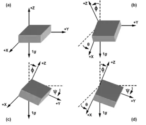
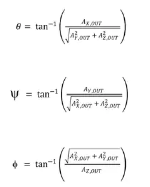
When the gyroscope values were examined, it was observed that the output values were increasing over time even through the MPU6500 module was stationary. There were two options to solve this issue, either apply a time-based filter to correct the gyroscope output or process the accelerometer values through trigonometry relationships. The Latter method was used. The equations used in the code can be seen in the figure below.
The last part in the loop function is repackaging the data in a structured form and transmitting it to the RC car Arduino.
RC Car
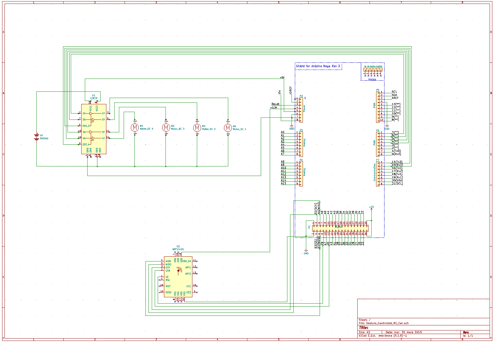
The RC car circuit consists of an Arduino Mega 2560, an NRF24L01 transceiver module, a Kuman KY58 L293D motor drive shield, and 4 DC motors. A 5V power bank provides power to the circuit, and a 6V external power source powers the motors. The wiring schematic can be seen below.
In the code's setup function, the four motor speeds are initialized to 230, 25 less than the maximum speed of 255. 230 was an optimum speed for the external power supply used, otherwise the circuit will power-out at a higher speed.
The radio transceiver is then turned on and tuned to the same address as the transmitter. Unlike the transmitter however, the receiver requires the selection of a pipe channel because receivers can communicate with up to 125 different transmitters. The range and transfer rate are set similar to the transmitter. Lastly, the NRF24L01 is commanded to start listening since it is the receiver.
motor1.setSpeed(230);
motor2.setSpeed(230);
motor3.setSpeed(230);
motor4.setSpeed(230);
radio.begin();
//set the address
radio.openReadingPipe(0, 00001);
radio.setPALevel(RF24_PA_MIN);
radio.setDataRate(RF24_250KBPS);
//Set module as receiver
radio.startListening();
}
Five functions are created for the car moving scenarios. These functions will be called for in the loop function depending on the hand gesture.
motor1.run(FORWARD);
motor2.run(FORWARD);
motor3.run(FORWARD);
motor4.run(FORWARD);
}
void backWard() {
motor1.run(BACKWARD);
motor2.run(BACKWARD);
motor3.run(BACKWARD);
motor4.run(BACKWARD);
}
void Stop(){
motor1.run(RELEASE);
motor2.run(RELEASE);
motor3.run(RELEASE);
motor4.run(RELEASE);
}
void clockWise(){
motor1.run(FORWARD);
motor2.run(BACKWARD);
motor3.run(BACKWARD);
motor4.run(FORWARD);
}
void counterClockWise(){
motor1.run(BACKWARD);
motor2.run(FORWARD);
motor3.run(FORWARD);
motor4.run(BACKWARD);
}
In the loop function, a 'while loop' is used because the loop needs to run infinitely, unless the transceiver communication is lost. The data received from the transmitter were processed through a series of 'If' statements to determine if the RC car should move forward, backward, clockwise, counterclockwise, or stop.
while (radio.available()) {
radio.read(&receive_data, sizeof(receive_data));
if ( receive_data.yAxis >= 30 ){
forWard();
}
else if ( receive_data.yAxis <= -30 ){
backWard();
}
else if ( receive_data.xAxis >= 30 ){
counterClockWise();
}
else if (receive_data.xAxis <= -30) {
clockWise();
}
else {
Stop();
}
}