Posture correction Device
A wearable posture correction device that tracks real time posture inclination angle. This device can also collect data and display it on a mobile application.
After months in isolation, many of us have been spending countless hours in front of our computer screens. This has resulted in a variety of effects on our health. In my case, I have been recently noticing some back pain that was likely a result of my poor posture. Initially, I tried using a posture corrector, however, this was not effective. It only seemed to weaken my muscles and give them something to depend on rather than strengthening them. It seemed that the only way to consciously improve my posture is by training my muscles.
This got me thinking. What if there was a way to develop a device that could maintain correct posture without giving our muscles something to depend on? Well, I began utilizing my knowledge in C++ and Python to develop an application that can be used to form healthy sitting habits.
The Hardware Used in the project:
- A gyroscope to measure the inclination angle of the user’s posture.
- An ESP32 microcontroller to process the data and send it to the application.
- An Android phone that is capable of connecting to WIFI and running custom applications.
Implementation Details
MPU6500 Accelerometer / Gyroscope
The MPU6500 module consists of a 3-axis gyroscope as well as an accelerometer along the 3-axes. The gyroscope is able to detect angular rotation using micro electro-mechanical system (MEMS) technology. When the gyros are rotated about any axis, a vibration is detected by the MEM within the MPU6500 chip. The MEM consists of a series of capacitors with small gaps in between them. As the MEM starts to vibrate, the gap between these capacitors increases. This change in capacitance is then detected and transmitted to the microcontroller.
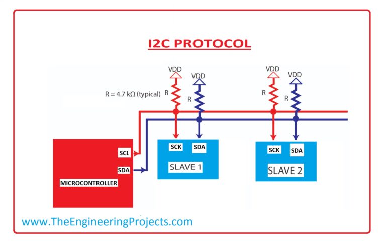
The MPU6500 module utilizes a bus to communicate with the microcontroller. This bus is called an I2C because it is an integrated circuit (IC) that has more than one chip connected to it. The I2C uses two wired connections, serial data (SDA), and serial clock (SCL), to communicate between the master (Arduino) and slaves (MPU6500 and MPU9250 chips) as seen in the image below.
To establish communication between the master and slave(s), the 'slave address' and the 'register address' within the slave need to be identified. The image below contains an example of how data is read from the slave.
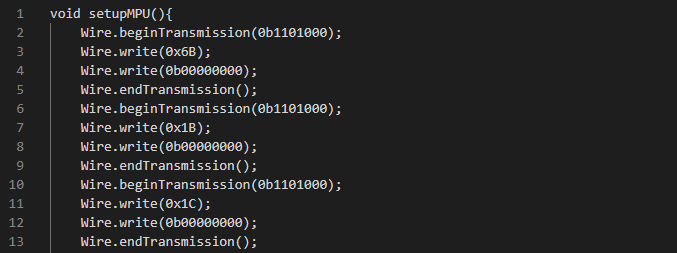
The command on line 2 calls for the slave address, followed by line 3 where the register address is identified. line 4 indicates the sensitivity and reading radius required (0 to 180 degrees). Lasty, the fifth line ends the communication between the master and slave. Note that the MPU6500 module datasheet lists the slave addresses, register addresses, and settings.
The code discussed above is not included in the Arduino code, rather, it is called through the 'Wire.h' Library.
Wiring and Coding
Back Brace
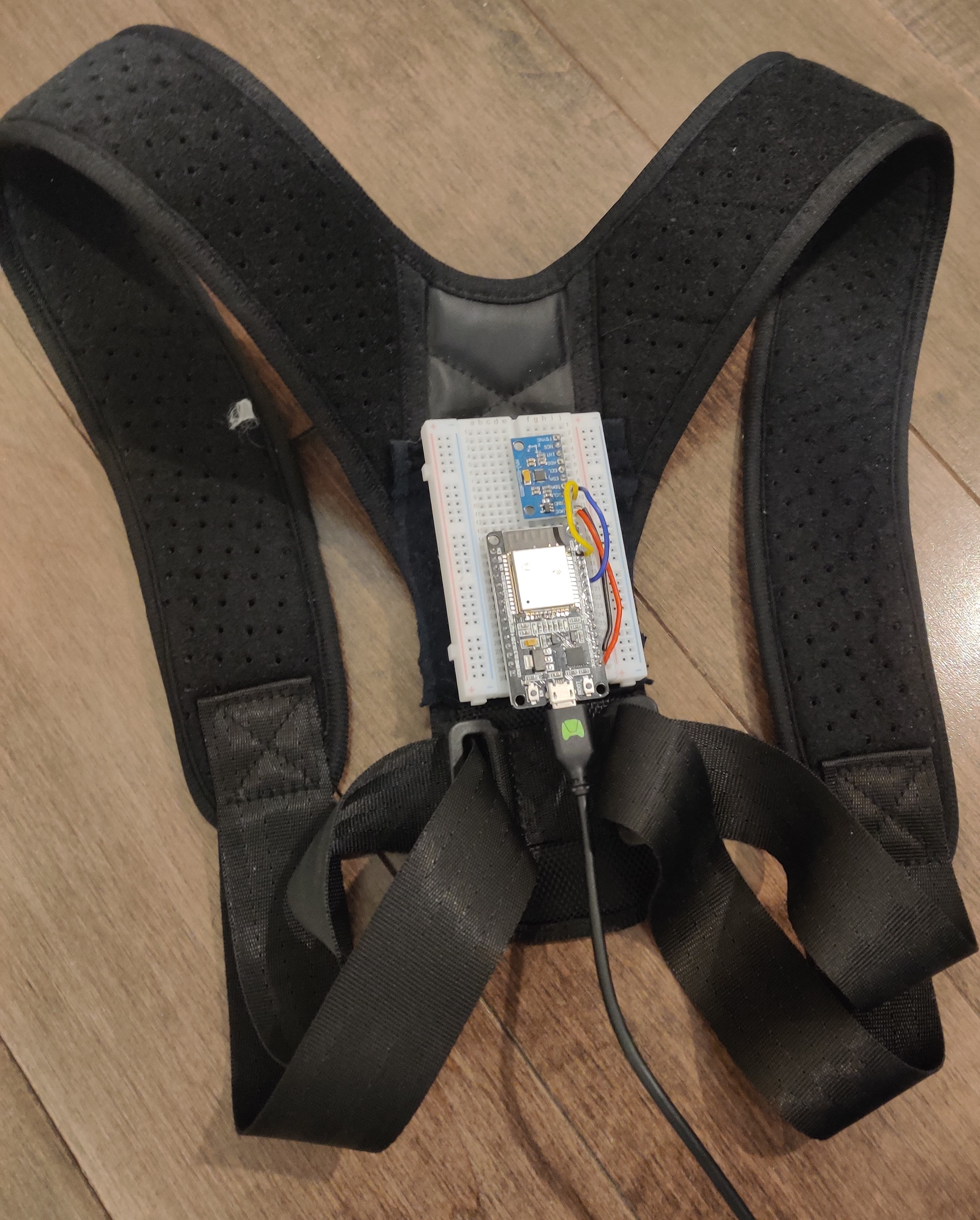
The back brace circuit consists of an ESP32 microcontroller and a MPU6500 module. A 5V power bank is used to power the circuit via the microcontroller through a micro-USB connection. The wiring schematic can be seen below.

The ESP32 and gyroscope is then attached to a posture brace. A picture of the brace used in this project can be seen below.
In the code's setup function, the I2C bus is first enabled by calling the function 'Wire.begin()', followed by initializing the MPU6500 chip (variable name 'accelgyro'). Then the ESP microcontroller is connected to the internet with the ‘Wifi.begin(ssid,password)’ command where the WiFi username (ssid) and password are hard-coded. Finally, the microcontroller connects to the server host and phone application with the ‘client.connect(host, port)’ command, where the host is the phone’s IP address, and the port is a four digit domain number. Note that the ssid, password, host, and port variables were initialized at the beginning of the program and are not shared due to privacy concerns.
Wire.begin();
accelgyro.initialize();
// Connecting to the Wifi.
WiFi.begin(ssid, password);
client.connect(host, port)
}
The values of the accelerometer and gyroscope are obtained from the loop function. The gyroscope values are divided by a constant that is appropriate to the gyroscope sensitivity setting.
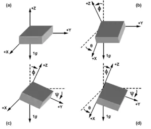
When examining these values, it seemed that the output values of the gyroscope continued to increase over time, whereas the MPU6500 module remained stationary. There were two methods that could be used to solve this issue. One method is to use a time-based filter to correct the gyroscope output, and the other method is to apply trigonometric relationships to process the accelerometer values. The Latter method was used. Note that the equations used can be seen in the figure below.
// Creates a client that connect to the server
WiFiClient client
// Collect readings
accelgyro.getMotion6(&gz);
// Apply gyro scale from datasheet
gsz = gz/gyroScale;
// Calculate accelerometer angles
arz = (180/3.141592) * atan(sqrt(square(ay) + square(ax)) / az);
// Send data to the server host (phone)
client.print(arz);
delay(1000);
}
The last part in the loop function is sending the data to the application. This is done with the 'client.print(arz)' command, where arz is the inclination angle variable.
Phone Application Structure
The Application consists of a main page, observation page, and a results page. The main page allows the user to select a 10 minutes, 15 minutes, or 20 minutes session. The observation page is where the user can start their session. The graph’s x-axis values correspond to the session length. The observation page also displays the average inclination angle of the user’s back throughout the session. Lastly, the results page displays a graph of the entire session, the average inclination angle of the user’s back, and the lowest inclination angle recorded. Screenshots of the application can be seen below.

The script for the application is written in two main files: a python file (.py ) and a kivy file (.kv). The python file controls the commands and function of the application whereas the kivy file designs the interface and interaction.
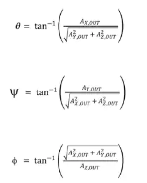
The kivy file is not structured like a python code. An example of how a button is programmed in kivy language can be seen in the picture below.
- 'On_press' calls for the 'root.exit()' from the python file when the button is pressed.
- 'text' is where the text on the button is coded. 'size_hint' dictates the size of the button.
- 'pos_hint' declares where the button is located on the page.
- 'Label' is used to print out information. The label in the picture is used to print out dynamic information, which is why 'text' is left blank. The id is the variable named used in the python file to send information to this label.
Due to the complexity and length of the phone application code, it will not be discussed thoroughly. Rather, important python libraries and functions will be highlighted; and the code’s data flow will also be discussed. The Phone application code files are provided below for download.
DOWNLOAD PYTHON FILEDOWNLOAD KIVY FILE
Libraries
Socket
A standard python module that is used as an inter-process communication (IPC) method to share data between the phone application and the ESP32 microprocessor. Socket also enables the phone application to act as a server host for this project.
Operation System (OS)
A standard python module capable of utilizing operation system functions. The module is called for in the program to incorporate the pathing functionality, absolute pathing specifically. Absolute pathing is critical to this project because it eliminates any 'file not found' issues that are likely to occur. This is because the original script that was created on a windows 10 operating system was moved to a Linux operating system in order to generate an APK file which creates an executable setup file used to install the application on the android phone.
Therefore, the usage of the absolute pathing is crucial because it maintains a fixed file pathing regardless of the operation system.
Kivy
The Kivy module is the backbone of the phone application. It is an open-source software that allows applications to be developed with python code. The advantage that kivy has over other modules is that it has cross-platform compatibility. This means that the application works on various operating systems such as: Windows, Mac, IOS, Android, and Linux. Kivy is also compatible with many python modules.
Kivy has dozens of sub modules available. The ones used in this project are:
- kivy.App : The main loop of the script.
- kivy.Lang : Allows for the python language to interpret the kivy language.
- kivy.uix.Screenmanager : This module is for managing multiple application pages/screens. It is also responsibly for the transition in-between the pages.
- kivy.uix.boxlayout : arranges the application's 'children'. The 'children' are programable interfaces such as buttons, text displays, etc.
- Kivy.uix.behavior : Imports 'children'. It was used to import buttons in the application.
- Kivy_garden.graph : Enables the use of graphs into the application.
- Kivy.clock : Required to execute timed functions since standard python time functionalities are not compatible with kivy.
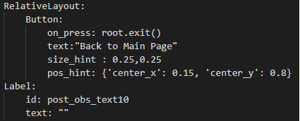
Data Flow
The data flow of the program is simple. Raw data is generated by the MPY6500. Then the data is processed in the ESP32 microcontroller into inclination angles using the equations listed above. The processed inclination angles are then transmitted to the phone application via internet WiFi connection. The data is then stored and processed further to create plotted graphs that displays the average posture inclination angles.
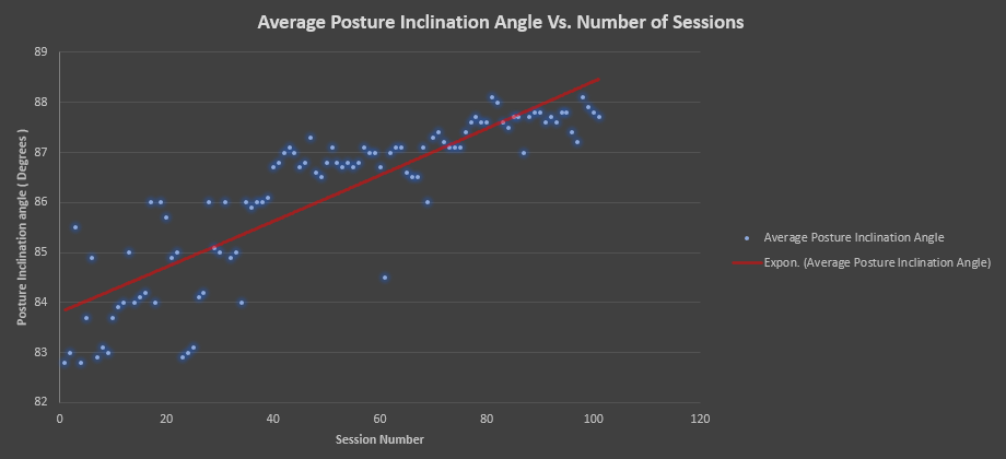
Results
By observing the graph above, two trends can be highlighted from the 100 sessions completed. First, the average inclination angle has improved and is approaching the ideal 90 degrees value. Second, the results became more consistent when compared to the initial results. Therefore, it can be concluded that the device was a success since my sitting habits has been improved.